Driving excellence in aseptic fill-finish: Our strategic partnership with Stäubli Robotics
At 3P innovation, we engineer automation with purpose - solutions that don’t just meet the demands of aseptic manufacturing but redefine what’s...
4 min read
In this blog, Carl Jones, Project Group Manager at 3P, talks about his passion for steam railway locomotives and how this links to some of the projects he's worked on at 3P.
 Man’s greatest piece of engineering?
I’ve had an absorbing interest in and passion for steam railway locomotives for as long as I can remember. A career in Mechanical Engineering was the obvious choice for somebody who had always sought out as much technical information as possible about man’s greatest piece of engineering. Man’s greatest piece of engineering? Is this an outrageous claim? No! Let me explain why…
My colleagues at 3P innovation will happily rib me mercilessly of course. Even our Managing Director will lower himself and join in! However, rather than rise to their friendly jibes, I can only pity their ignorance – sorry Tom… I am of course able to explain why the steam locomotive contains all of the fundamental points of engineering which have driven mankind’s progress since the Enlightenment and for all that is the closest man has ever come to creating a living machine. A steam locomotive at speed under power is a brilliant manifestation of the conversion of raw energy. It performs a type of alchemy by combining the basic elements of fire and water to produce motion and ‘poetry of motion’ at that. As a well-designed and finished machine, a locomotive can be very pleasing to look at – equal to any famous artwork - and yet it has the advantage over a painting or sculpture of being animated and has a sound and presence that makes onlookers step back in awe when it passes.
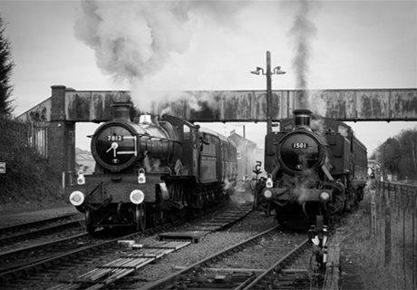
In my spare time, I am a qualified fireman at the preserved Severn Valley Railway which is a former Great Western Railway line on the border of Shropshire and Worcestershire and is now a significant tourist attraction, remaining so even through the current pandemic. The steam locomotives on the railway work moderately hard hauling trains of tourists throughout the year. As well as being a fun day out, the Severn Valley Railway is an important living museum showing how railways were once operated and their effect on the social history of the United Kingdom.

The Author at the (Fireman's) controls of 7812 'Erlestoke Manor' leaving Kidderminster in December 2016. Photo by kind permission of Jason Houlders
Steam locomotive engineering and design features static force analysis, kinematics, balancing of reciprocating and rotating masses, thermodynamics, fluid mechanics, feedback loops, suspension, casting, forging, fabrication, riveting, machining, fine finishing and many other processes.
You might not be aware or have even considered that the steam locomotive generally possesses a floating crank axle, supersonic steam flows and firebox operating temperatures well in excess of the melting point of the materials of construction. This was all being done 100 years before the modern and perhaps better known similar example in jet engine turbine blades.
After all that, you operate it with a box of matches, a shovel and some large hammers! Am I beginning to convince you?
Having spent a good deal of my spare time studying the very broad range of subjects in locomotive engineering, it will come as no surprise to you that I happen to spot all manner of parallels in my day job at 3P innovation. I frequently review the technical solutions we design in weighing, fluid and powder handling, component handling, forming and welding processes and can relate these to solutions developed 100 years ago by clever Mechanical Engineers solving different but similar problems on the locomotive.
Almost anyone reading this article will be familiar with the crank and slider mechanism so obvious on a steam locomotive:

Author's drawing of working parts of Manning Wardle Locomotive 'Warwickshire'
A connecting rod couples a cross head and piston which reciprocates linearly in a cylinder to a crank pin which rotates about a centre. Remember that a locomotive is double acting – steam pressure pushes on each side of the piston alternately whilst the opposite side is exhausted. Most engineers are familiar with the automotive terms Top Dead Centre and Bottom Dead Centre but on a locomotive this is more appropriately Front Dead Centre and Back Dead Centre. Clearly when the cross head is at either of these points, the crank pin, connecting rod and cross head all lie on a common, nominally horizontal plane. (It is often inclined on a locomotive as in the example shown above or even offset slightly but we won’t worry about that for now… You can ask me about that later…)
If we consider the angle of the crank as at moves around from 0 to 360 degrees, let us say that 0 and 180 degrees will correspond to the dead centres.

Crank angle 0 degrees

Crank angle 180 degrees
Many engineers will have overlooked the fact that when the crank is at the 90 or 270 degree position the cross head and piston will NOT be half way along it’s travel. The connecting rod is at an angle, it forms a sort of hypotenuse, and therefore the piston position is offset rearwards by a small amount.
Crank angle 90 degrees
The shorter the conrod, the more pronounced this effect. The effect may appear benign but in fact it significantly taxed the minds of our forebears the locomotive engineers. The reason is because they wanted to achieve equal distribution of power between the forward and rearward strokes of the piston. Very cleverly, good valve gear design can achieve timing compensation so that the events in the piston cycle – admission of steam, cut off of admission, exhaust and compression – occur more evenly in front and rear halves. This is achieved by the careful selection of a number of other links which generate similar errors to our connecting rod but at different phases. When combined these can be made to produce a partial cancelling effect.
At 3P, we recently needed a mechanism which had to move between an upper and lower position rapidly yet needed significant stiffness in its upper position. A precision operation was to be carried out when the mechanism was at its top dead centre. A crank and slider just like on a locomotive seemed the obvious choice. A servomotor was connected to the crank and adjustment was provided on the connecting rod to control the top dead centre position.
A further requirement was the ability to know where the tooling at the top of the mechanism was in space during the motion. This was because a further independent secondary mechanism had to closely follow the position of the first. Out came the position tables! Or perhaps they would have done if we were in the Great Western Railway drawing office in Swindon in 1905…. These days of course we can calculate the positions with some nice geometry using our knowledge of the ‘hypotenuse effect’ mentioned above and the results can be tabulated or graphed really quickly in Excel. You see – it’s exactly the same problem that the great designers of steam locomotives, W H Pearce, G J Churchward, H Holcroft, H N Gresley faced all those years ago…
Mechanical Engineering has not changed, but that doesn’t mean it is stuck in the past. Ingenious application of fundamental principles will continue for many years to come.

At 3P innovation, we engineer automation with purpose - solutions that don’t just meet the demands of aseptic manufacturing but redefine what’s...
Pharmaceutical extrusion is a critical enabler in the manufacture of advanced drug delivery systems, from long-acting injectables to solid implants....

Before delving into some technical details of cell and gene therapy manufacturing, it’s worth pausing to reflect on the human stories that drive this...