From Disruption to Reinvention: The Story of API-in-Capsule Technology and Its Future
From Disruption to Reinvention: The Story of API-in-Capsule Technology and Its Future This article traces the evolution of API-in-capsule (AIC)...
4 min read
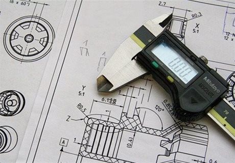
In this blog, one of our mechanical engineers discusses how CAD packages have changed engineering drawing. He talks about the importance of drawings and how modern-day CAD packages could further improve the design process.
I’ve been using various CAD packages over the last 25+ years of my engineering career, from starting out using an old version of AutoCAD 10 with the puck and tablet, through various iterations of AutoCAD, before moving into the now with the all-singing, all-dancing parametric CAD packages. Over the years there has been a quantum jump in what you are able to do with these CAD packages (animations, structural analysis, CFD, parametric modelling to list just a few), but one area that seems to have been left behind is the ability of the designer to produce a top notch 2D engineering drawing.
There are a number of drawing types associated with the mechanical design process. The two main types are assembly drawings, and detail drawings.
An assembly drawing shows, in quite some detail, how the various components fit together. It should include the overall dimensions of the assembly, any setting dimension once built, a parts list, and corresponding identification balloons.
An engineering, or detail drawing, is used to clearly and accurately convey all of the geometric features of a component, so that the manufacturer or engineer can produce it. Things such as the required material, surface finish, and any secondary process requirements such as heat treatments and coatings would be specified on here.

‘Why do I need a drawing?’ is a commonly asked question in this day and age. Yes, you can send a model file directly to the manufacturer who can load it into their CNC machine and accurately manufacture the required part. But how do you specify surface finish, and any secondary finishing processes such as anodizing? How do you highlight dimensions that are critical and will need checking post manufacture? How do you highlight any revisions that have been made to the part during the development process?
If you’re building a machine, or an assembly within a machine, a good assembly drawing is far more useful than any CAD model. Everything is laid out clearly, with all of your setting dimensions visible. There should be no need to interrogate the master model for measurements, or part numbers. Any key assembly tasks and additional notes can be highlighted here.
Customers will always need drawings to be able to maintain the finished machines once they are being put to use out in the real world. Okay, you could produce a fancy animation of how it all fits together, but that’s not really practical in a workshop environment.

So you’ve come to the conclusion that you still need to produce a 2D drawing. In the days before CAD packages became commonplace, you would have sat at your drawing board with all of the associated paraphernalia (different pens, rulers, callipers etc.) and got to work. Some of the old manual drawings I’ve seen over the years were works of art. Heaven knows how long they would have taken to produce. Now, you simply create a 3D model of the component that you require and use your favoured CAD package to quickly create a drawing of the component.
‘All is good’ you think, but it’s at this point where some of the issues with using the standardization of the CAD package come into play. It’s great how quickly you can layout a drawing; making sure all of your text is uniform height, that all of the dimension arrows are the same size, and every drawing that you produce is in the same format and so on. But, delve a little deeper and you start to find that not everything is as rosy as you first thought. You begin to come across some issues that wouldn’t exist with a manual drawing, and you find yourself having to manually update things anyway.
There are lots of other areas of drawing creation with this software that whilst making things far easier than they would have been on the old fashioned board, would seriously benefit from some additional functionality. It’s almost as if the software company have ticked off that feature on the first attempt, and don’t see any need for further improvement. Things like hole tables are great, but origins can’t be rotated, leaving two dimensions sets with the same identifiers. Break a view to fit it onto a smaller sheet to make everything readable and some of your dimensions disappear. Auto balloon an assembly drawing and it looks like an explosion in a balloon factory.
Use the software for any period of time and you’ll come across more and more of these little challenges.
One example to highlight is sectional views in an assembly drawing. In the package that I use, Inventor, every component is hatched, with the exception of some standard components such as screws and bearings, at the same scale but different angles. Some of these angles are at strange degrees. You have to tidy up the sectional view, because the scale of the hatch has no relationship to the size of the components being hatched, and some appear not to have been hatched at all. Every component in the assembly is treated as a unique occurrence, and every component is hatched with a unique pattern.
Additionally, some parts will be hatched that, if adhering to general draughting standards, shouldn’t be. Things such as shafts though an assembly or casting web need to be manually switched off. The sectional views can be dragged around the sheet, but the direction arrows don’t update, leaving you with no standard view available.

The death of the engineering drawing has been greatly exaggerated by the various software companies pushing digital prototyping. They’ll be here for a while yet. There is more to producing a component than just producing a 3D model & sending it to a CNC machine. For rapid prototyping this approach works great. But certain components will always require inspection reports on key dimensions to suit surface finish checks. Specialized secondary processes will still be required, and will need specifying correctly.
Modern CAD packages do make producing drawings far easier that it would be on a drawing board, but the designer / draughtman is still restricted by the limitations of the software. It would be nice if the software companies would improve the drawing side of the software, rather than constantly updating the user interface or adding new features found in their competitors’ packages. A smart move would be to bring engineers into the programming process and seek advice on what is required in a real world environment.
Additionally, the end user has to be aware that all software comes with limitations. Some forethought is necessary before diving in to create drawings, as well as consideration over whether the solution you are trying to present will help improve the finished product.
Because it’s so much easier to create all of your drawing views, superfluous views can easily be plastered over sheets, making things look untidy. They should also be prepared to do some manual intervention to the drawings to ensure that it is clearly presentable, and shows everything that is required. The software can’t tell if information missing or obscured to the user.
Maybe one day these issues will be addressed, but until then, we’ll all have to accept that things aren’t perfect, and appreciate the advances that have been made to make this part of our job a lot easier than it’s been before.
And don’t forget, you’ll always get the occasional old school designer asking “Why have you done it like that? Would you have done it like that on the drawing board?”.

From Disruption to Reinvention: The Story of API-in-Capsule Technology and Its Future This article traces the evolution of API-in-capsule (AIC)...
The revision of EU GMP Annex 1 has redefined expectations for sterile manufacturing across the life sciences sector and nowhere is this felt more...
Today’s pharmaceutical landscape positions 'sustainability' as an operational imperative. Manufacturers face increasing regulatory, societal, and...