Inside 3P innovation’s Latest DPI Blister Filling and Sealing Platform
In this interview, Carl Jones, Projects Director at 3P innovation, discusses the company’s latest advancements in blister filling and sealing...
7 min read
In this blog, Dr. Dave Seaward (Director of Projects at 3P) discusses the way that modern CAD systems and 3D printers have changed forever the workflow for mechanical design engineers, and he posits that 3D printers are the ultimate in delivering “fail early, fail fast”.
This follows on from his previous two blogs ('Why you should embrace failure: from human-powered airplanes to anti-HIV vaginal rings' and 'Has Pharma finally found its 'skunk'?').
 Humble beginnings
When I entered industry in the early 1980’s Computer Aided Design (CAD) had just arrived. Large organisations had invested in huge blacked out rooms full of green monochrome screens driven by CAD stations costing more than a family car. The drawings were basic 2D and the workflow “clunky” to say the least, but CAD had arrived. In parallel there were traditional drawing offices full of row upon row of drawing boards populated by engineers, designers and detailers working with pencil and rubber in equal measure. Each drafter owned their own set of propelling pencils, French curves, inking pens, protractors, rules, dividers, trig tables, calculators, rubbers, set-squares, compasses (with extensions for those big circles), letter and number stencils etc. Indeed, I was given my father’s “precious” set of Staedtler drawing instruments that were bought in the early 1950’s during his father’s time as an apprentice draftsman.

These drawing offices (DO’s) felt old fashioned even to a fledgling engineer: the air hung with the smell of ammonia from the A0 copying machines of the day, mingled with stale cigarette smoke. The once white walls were browned by decades of nicotine exposure – these were the days before smoking in work environments was outlawed.
The work flow reflected the technology of the day. The design authority was either a senior draftsman (and “yes”, they nearly always were men) or a degree educated engineer. They supervised the process, attended design meetings and walked up and down the rows of drawing boards surveying the designs as they progressed. For a skilled engineer it was possible to almost instantly spot issues on an A0 drawing from several metres away. They would stop as they passed by to chat to the designers. They would tweak a detail here or there, or stop to offer advice. The designers were highly skilled and needed to be able to think in 3D – “spacial awareness” was the key to their success. The designers generated layout designs incorporating all the individual piece parts. Sections were drawn of key areas. For automation projects actuators were drawn at extremes of motion to try to avert clashes when the machine was built.
In addition, there was a certain degree of artistry required to generate a “good looking” layout design. Once layouts had been signed off by the engineering leadership team the detailing began. Teams of less able detailers would then work with the designers to generate detailed drawings for each part. Many companies became reliant upon contract detailers that could be pulled in towards the end of a project’s design phase. In some industries inkers would meticulously trace over the pencil drawings in ink. In other industries teams of designers acted as “checkers”. The drawings would then be sent to document control to be stored and issued to production for manufacture… then the real “fun” began.
As a young engineer learning my trade there was a certain fear of mistakes because you quickly learnt the cost of a simple drafting mistake. It is as true today as it was then that the typical lead time for a one-of-a-kind machined part is around 4-8 weeks, depending upon its complexity. Parts needed to be simple in form such that they could be milled or turned on predominantly manual machine tools. Imagine having worked hard on a drawing board to complete a design, then spend weeks waiting and expediting suppliers to find an error when the parts come in. In a worse-case scenario, you might have to wait another 8 weeks for a replacement part.
So, what used to go wrong (and still does to a lesser extent)? In no particular order:
Even when parts assemble, for custom machinery, there is the make work phase which can take months of development. The end effectors typically need fine adjustment (fettling) to match the part being handled. Often times parts would clash at end of stroke in 4D space due to a clash not spotted on a 2D drawing. Machinery development was very much an emotional roller coaster that could take months to turn the machine that couldn’t run into to the one you were proud to send into a client factory. Oftentimes the changes were subtle but they made all the difference.
It is true to say that back in the 1980’s and 1990’s machinery development suffered from “fail-late, fail-slow”. Development could often be very late and cost significantly more than expected.
During the intervening decades 2D CAD (the electronic drawing board) became main stream, this was replaced by 3D wireframe models which in turn gave way to true 3D models. Document management has been automated within the software as has detailing. It is possible for the CAD to flag metal on metal clashes. As you can see if you visit our virtual showroom modern 3D models are essentially “digital twins” of the real machinery, Virtual Reality (VR) also enables a virtual walk around machines prior to build. Within modern CAD packages it is possible to exercise gears, cams and mechanisms. This has revolutionised mechanical engineering workflow.
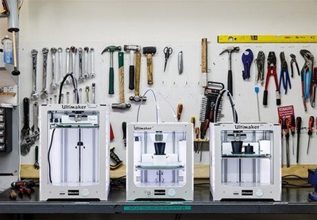
In addition, the cost of 3D printers has plummeted. 3P have invested in a range of printers from £40,000 to less than £200. All serve a purpose. Engineers are now able to hold a part they designed on the same day.
The start of the process is very similar to all those decades ago. Typically, a senior engineer will act as the machine architect. A group of engineers will meet to debate the overall machine concept led by this architect. Machines are split into modules and engineers are tasked with coming up with sketch layouts in CAD. These sketches focus on the overall size and form of the module. Design reviews are used to refine and optimise the layout design – these typically use peers not directly involved in the project. 3P have a number of design gates and reviews to ensure robust designs. Once passed off (often via client design qualification) detailing begins. Detailing is now semi-automatic and isnt the huge task it used to be. It shouldn’t be surprising that this task that was once the preserve of less skilled designers and sub-contractors has been all but automated by software.
This exposes one of the key differences across the decades: the skill level required has increased. Not only does a good mechanical design engineer have to be able to think in 3D but they also need to be expert in driving modern CAD packages. 3P’s experience is that there are fewer and fewer roles for less skilled individuals. Our engineers typically have a Bachelors and a Masters Qualification from one of Europe’s best Universities. Once detailed 3P perform what we call a “reverse build”.
An engineer not involved in the project assembles the models of the individual parts within the CAD system. This ensures that parts can be assembled and that parts go together (tolerances/hole alignments etc). Mistakes are usually self-evident within the CAD environment. One of the other key changes is the way 3D printing is used to de-risk projects using the fail-early, fail-fast paradigm.
It is now possible to design a part and hold a functional plastic version of that part on the same day. The costs of these parts are trivial. Hence 3P’s 3D printers are continuously producing parts simply for trials. Where there is uncertainty between two concepts, we will now often print both and use real world experience to inform the design decision. We will often defer machining metal parts (especially for end effectors) until after the machine has been initially run-up with 3D printed parts. Metal 3D printing is available but as yet the costs outweigh the advantages for 3P: like plastic 3D printing these costs will only fall. The delay during development waiting for replacement parts has been significantly reduced as we can print versions of the same part and see what works. Sometimes we will run a design of experiments to understand the relationship between a part’s design and a factor important to our client.
The work flow is now very different to several decades ago, and it is because 3D printers mean that engineers can iterate at a rate (and affordable cost) unheard of 20 years ago. Part complexity has also increased due to the advances in machine tools that can take 3D models from CAD files to generate parts. Decades ago non-essential features such as chamfers and radiused corners were discourage due to the time to design plus the additional machining operations. Now one can add these features with a couple of clicks, and modern NC machine tools will happily add these features for practically no extra cost.
Not really! Machines now bolt together with less fitting. There are less assembly errors and first-of-a-kind assemblies can actually be assembled. We still spend time, but crucially less time, debugging the equipment once built. Clients are still often confused why this “back-end loaded” risk still exists, despite all our prototyping. This is simply a reality of first-of-a-kind automation. Thankfully rapid prototyping means we can “ring the changes” same day/next day. It is now common place to carry out factory acceptance tests with one or two rapid prototypes in place which are swapped out for the metal parts during the transport period. There is one negative trend, however, that we have noticed: younger engineers who have been brought up with 3D printers now occasionally design parts that cannot be machined using conventional machine tools. Training in conventional machining has become important to prevent delays due to parts that cannot be machine – a new form of fault rarely seen 30 years ago – the unmachinable part.
Engineers are known for their “tinkering” and also for that rare talent of being able to use their ingenuity to fix broken household items. For some light relief please take a look at Dilbert’s “Knack” on YouTube. The author’s own home experience has changed when a plastic part fails on some domestic item… in times gone by Superglue™ was the go-to material to try to fashion a repair. Invariably the glued joint would fail. Now the parts is measured, sketched up in CAD, then printed on a home hobby machine. Additional plastic can be added to strengthen the part in critical areas to avoid a repeated failure. All of this would have been impossible just a few years ago.

In conclusion, the way mechanical design is carried out has changed forever. Modern CAD and 3D printing enable fail-early, fail-fast. The digital twin has allowed more complex parts to be designed quicker and with lower risk of design error. The last 30-40 years have seen a revolution in the way design is conducted: one can only imagine what the design process will look like by mid-century. Will digital twins be so good that “failing”, fast or otherwise, is no longer a thing?
In this interview, Carl Jones, Projects Director at 3P innovation, discusses the company’s latest advancements in blister filling and sealing...

From Disruption to Reinvention: The Story of API-in-Capsule Technology and Its Future This article traces the evolution of API-in-capsule (AIC)...
The revision of EU GMP Annex 1 has redefined expectations for sterile manufacturing across the life sciences sector and nowhere is this felt more...